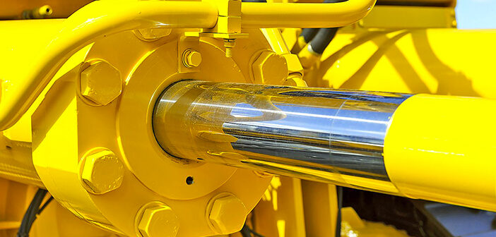
Hydraulics is a branch of fluid dynamics that is applied to mechanical engineering and deals with the study of energy transmission through pressurized fluids and in particular through hydraulic oil.
The oil flow generated by a pump within a hydraulic circuit is used to move a hydraulic motor depending on whether the desired effect is linear or rotary.
The simplest hydraulics is that of the cylinder, or the wheels of earth-moving machines such as large agricultural tractors and excavators. Again, the winches to hoist the fishing boats’ nets.
Hydraulics is also represented by unified symbols that allow designers to draw circuits and systems in a universally understandable way.
In hydraulics, each symbol represents a function and has no reference to the manufacturing characteristics of the component. For example, pumps are represented by the same symbol regardless of their construction.
Complex functional symbols are created by combining the fundamentals and can be depicted in any orientation.
Hydraulics presents in its schemes combinations of symbols and connections in order to represent complete systems or their parts.
The symbols shown in a diagram represent the components in the rest position, unless otherwise indicated in writing.
When two or more symbols are joined to form a functional module, they must be enclosed in a dotted rectangle.
It is not precise that the hydraulic symbols contain letters or numbers except for the symbols of the electric motor and the endothermic one.
A small dictionary cannot ignore some “families” of components.
The pumps are represented by a circle and the direction of flow is indicated by a black triangle oriented inwards.
The cylinders use as a basic symbol a rectangle of size L x 2L containing another rectangle of size L x 0.25L which is the piston and a pair of 0.2L spaced rings (rod and rods).
The valves are represented by a square where the main connection is indicated.
The distributors (on, off, proportional) and directional servovalves use a group of adjacent squares in which the connections between the connections are drawn and the symbols of the control devices, the return springs and the notches are placed on the outer sides of the term squares of arrest.
In this document you can find all the symbols relating to the different devices.


